Re: need help missing parts bed instructions wire .i need it
Elaborating further on the info given by MWU and Spudwheelie:
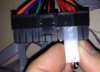
Here is an explanation of the colored wires for the power supply and what exactly each wire connection between the power supply and the GMax does. Hopefully, this will assist others in troubleshooting as well as expanding their GMax using the power supply provided (i.e. adding additional LEDs to the frame and having everything come on when you push the LCD power button.)
Color Wiring Explanation Main Power Supply Connector
Black - GND
Orange - 3.3-3.7v
Red - 5v
Yellow - 12v
Purple/Green/Silver = Signal wire (these are generally the colors used but vary depending on model. There will only be one of these.) When used in a computer, the main connector would be plugged into the mother board and the computer's power button would close the circuit between this wire and ground. Effectively, jumpering/completing the sensing circuit for the power supply to come on.
Here is how the GMax is using the power supply:
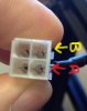
The GMax draws BOTH 5v and 12v from the power supply. The separate Yellow and Black wired connector powers all of the 12v components (steppers, heaters, LED light, etc.) and the 5v (red/black) portion of the 4 wire molex connector powers all of the electronics (LCD/Arduino/Ramps). The other two wires on the GMax molex connector are green and white. The GREEN and WHITE wires flow through the GMax power button switch. The MAIN power supply needs to have the signal wire shorted to GND in order to come on. This is what the printer power button is doing. It is taking pins 3 & 4 on the power supply and basically jumpering/shorting them like the motherboard example given above. This is what SpudWheelie, pointed out when he said to jumper 3&4 directly. The downside of jumpering directly is that you remove the power button functionality from the printer (but it is useful for troubleshooting) and have to directly plug/unplug the printer to turn it on and off (or have the plug plugged into an external switch).
As MWU pointed out, the reason why the LCD came on without the power supply being powered was because the printer was connected to the computer via a USB cable and the USB cable provides 5v VCC to the electronics via the Arduino's USB port. So power was flowing through the Arduino to the LCD and other electronics (i.e. endstops) None of the 12v hardware would have been operational though.
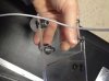
My LCD screen came prewired and I only had to plug the loose connector into the main electronics board. When I went to power on my printer for the first time, nothing happened. My four wire molex connector was correct and it was seated as far as it would go.- I traced the problem back to one of the wires connecting to the power button on the LCD screen. It had come loose, so it wasn't closing the circuit on pins 3&4 which is what turns on the power supply. This had come prewired so it took a moment to troubleshoot. As far as I can tell, the LCD power button does not illuminate it just routes the 5v vcc to the electronics.
Once all that is sorted out, you can take advantage of the extra power pins available on the MAIN power supply connecter. Here is one idea that proved both cool and useful to me:
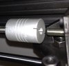
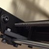
I wanted more light under the print head, so I removed the LED strip with 3 LEDs and replaced it with a double density LED strip containing 6 LEDs in the same space. While doing that I thought it would be nice to add another white LED strip overhead on the 18" horizontal frame (useful) and to also add add two RED LED strips under the 18" rails under the acrylic bed (cool) for really cool under lighting. I have a red/black XT so the red underglow under the acrylic bed is really cool. I even went as far as backlighting the frame in red, but that was a bit too much so I disconnected them. The LED strip on the extruder gets it's power right from the terminal block on the print head so that was an easy change. For the overhead and under bed lighting, I didnt want to use a separate power supply and I wanted the lights to come on when I powered on the printer, just like the extruder. So all of the LED strips were affixed to the frame and all of the black and red wires from the LED strips were capped and termintated with a single red & single black wire coming from the bundle. The red wire coming from all the strips (12v+) was plugged into a YELLOW (12v) port on the main power supply connector and the black wire was plugged into a black wire port (GND) on the main power supply connector. Now, when I turn on the printer via the LCD screen button all lights come on at the same time.
I will try and post pictures of my printer with lights and also show the connections but the forum is not retaining the pix I'm uploading.
Note: This same method can be used to draw 5v and 3v from the supply should you need to add additional electronics and such (i.e. camera). When adding components make sure you do not exceed the max current draw capable of the power supply.
Hope this helps.
Larry
 18.3 KB Views: 4,588
 150.4 KB Views: 4,589
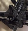 50.5 KB Views: 4,588