Print Quality Help

#1
Looking for guidance on improving print quality.

I've found a number of issues were addressed by tweaking the Slic3r settings.
But now I'm stuck and need suggestions for that last 10%. (to quote my wife) :)

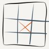
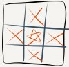
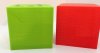
Tweaking settings example, printed 40mm test cubes had an annoying diagonal bulge that ran about 1/3rd of the way across the cube with the gMax Slic3r config.

Turning on 'Randomize starting points' under Layers and perimeters section of the Print Settings tab fixed the issue.

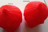
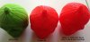
With and Without Randomize Starting Points


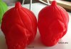
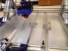
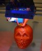
Test Jack-o Lantern Skull Looking Good While Printing


Updating to the E3D print head, replacing bent Z-rod and tweaking print settings eliminated print gaps and smoothed the visual appearance of prints, but they're still pretty lumpy/un-finished looking compared to my other printer.

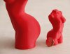
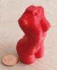
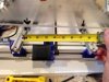
gMax OEM - Vision 3D - Updated gMax print comparison
 

Attachments

#3
Green "gMax OEM" print is reminiscent of a partially jammed jHead Nozzle.

An initial quick fix attempt is better cooling. Before setting up the included fan with blower I had strapped a large 80mm PC fan across the front of the extruder carriage.

I'm not sure what the Vision printer offers you that this one does not, but you can mess with the Slic3r settings for gMax to decrease the layer height to something like .15mm, .10mm, or .75mm for "higher quality" prints. Vision's X drive is threaded rod but its Y drive is belt so if that does offer precision it only does in 1 direction and not the other.

Start by simply decreasing the layer height for gMax in Slic3r and checking out the different levels of precision available to you...
 
#4
Don,

What is the difference in print speed between the two printers? I think the quality of the gMax print can be improved by dropping the maximum allowed acceleration values in Slic3r and then slowing it down overall. I find that the original bed is a bit sloppy due to the springs, the short distance between the v-wheels on the bed sled (both directions) and the long drive belt that tends to rise up a bit on the gear teeth every time the stepper motor changes directions, particularly when you are going fast. The decaying vibrations can be easily seen in the prints themselves. Your red print on the right seems to show those squiggles.

I have a plan to stiffen up the under carriage of my printer, while lightening the bed, changing it to a three point leveling system and maybe adding a heated PCB underneath. I have bought the PCB, two 1 meter lengths of the 20mm aluminum v-slot extrusion and solid v-slot wheels, but haven't got the details worked out for the rest. I am finding that the large prints I am doing (largest so far is 16" x 5 " wide in plan - laid out diagonally to print) can warp the bed in addition to curling themselves, so I am still scheming how to stiffen the bed enough to prevent the prints from bending it. Some of my issue may be that I am currently printing on a glass sheet laid on top of the original acrylic to help solve the flatness issue. The glass probably bends a bit more than the acrylic would by itself. Every big print brings its own challenges. Getting the filament to adhere well across the full diagonal of the bed on the first layer is just a wonderful way to spend an hour... I used 1/2" Lexan for a while with good results, but routing it out to make it lighter relieved some built in stress and caused a warp that I haven't gotten flattened out yet. I need to buy my wife a bigger oven so I have a bit more room in there for the Lexan warming.
 
#5
RPZ - couple of questions for you:

Are you talking about the ~$100 Monster PCB heatbed?
I had some plans for setting that up - It would involve an 18" square sheet a bunch of 2.5mm hex standoffs screwed to the top of it (this sets up a grid to prevent the PCB from sagging toward the middle). The PCB would go on top of it, 4 * 2.5mm screws for the corners, and like I said, the PCB would just sit on the grid of all the other standoffs so that it doesn't sag. Finally, one would use bulldog clips to attach a sheet of glass above the PCB. The corners would have to be chamfered as to not interfere with the screws.
The only issue I can think of with this is that the bed leveling screws are below all this and not accessible, but just make that lowest sheet more like 20" in the Y direction and you're set.
Plus, it would be highly beneficial to have a CNC router or laser available to make all those holes, it would be quite the chore by hand. The good part about it is that you only have to get the 4 corners lined up correctly, everything else just needs to be there and not all that precise...

Other than that, am I to understand you're printing PLA onto cold glass right now? How is that working out? This is something that I've been thinking about since I get poor extrusion with a first layer at ~197 degrees and would like to be doing everything at 215 - 230. With acrylic this would cause the print to permanently bond to it, hence the thought of glass. To twist this statement around, hey you're getting poor adhesion with PLA on cold glass... Have you tried increasing your temps?
 
#6
Ray,

I did buy one of the 18" square heated bed PCBs offered on eBay. No issues with the purchase, packaging was great, quick delivery. Only two minor issues. 1) the board does have a bit of a warp, but that was mentioned in the listing and expected. 2) the tight spacing of the circuit path on the board and the uniformity of coverage doesn't allow for holes to be drilled easily through the PCB except along the edges. There won't be a problem fitting the board into the available space between the gMax's uprights, and the dimensions can run long in the bed's travel direction.

I initially was thinking of sandwiching the PCB between two sheets of glass, but I am hoping a lighter solution will be evident with a bit more thinking.

I don't print on the bare glass. I am currently using a combination of blue painter's tape to cover the glass and a top layer of green masking paper from Home Depot. I apply Scotch permanent spray adhesive to either the taped surface (if I have taken the glass sheet off the printer) or to lengths of the paper, wait a minute and then stick the paper carefully to the taped surface. I trim it with a blade and then am ready to print, unless I have to attach the glass back to the acrylic bed (more tape). It is easier to pull the tape off the glass then clean up the spray adhesive. PLA adheres very well to the green masking paper.

I have also tried using Scotch repositional spray adhesive, and it works well for smaller prints on the green paper. Blue painter's tape alone also works well for smaller prints. However, the large prints need to be anchored down more securely (the paper will lift off and go with the print as it curls using the temporary adhesive spray) which is why I use the permanent spray adhesive. The paper doesn't lift with that.

My time at the printer is typically spent trying to get a good first layer laid down. Bed flatness and levelness are the bug. I use the skirt and the brim to quickly see if the print is going to stick completely around the perimeter. If it doesn't, I stop the print, peel off the plastic, make adjustments and start again. Slowing down the first layer manually with the knob next to the LCD screen helps as well. Once the first layer is down, I normally don't need to make further adjustments, and I usually bump the speed back up.
 
#7
Just to clarify, I was not suggesting drilling holes in the PCB. The 4 corner holes would be screwed down to the standoffs, as for the remaining standoffs, the board would simply rest on them in the hopes of leveling it out.

Have you tried printing on bare glass/ would you? For PLA I think you'd be able to get better results just by printing at 230 degrees. Make sure that the first layer is at that temperature, that's the most important part. It's a theory that I've got a gut feeling about, but I think you can save yourself a lot of hassle.
 

GORDON.LAPLANTE

Administrator
Staff member
#8
This is a great and detailed write-up.

@Don have you tried out our latest slic3r config files? Unfortunately you can't simply load them into slic3r and you have to instead copy the files into the slic3r directory. The path is mentioned in the details of the download.

Through all of our testing and prototyping we discovered a few things:

1. Cooling, when using PLA, is key. The faster you can cool the plastic, especially with overhangs, the better your quality.

2. Try speeding up or slowing down the print as its running. You can do this by turning the knob during a print and waiting for the print to complete about 20 moves. We have tried everything from 30mm/sec up to around 150mm/sec and 85 seemed to work for most situations.

3. The potentiometers run everything. One of our printers has the dreaded z-axis ridging going up the sides of the model. The ridging wasn't a layer shift problem and instead it looked more like a christmas tree where every 10 layers or so uniformly scaled in both directions. We literally tried everything mechanically and tweaked every setting in the slicing engine and we learned that the ONLY thing that had ANY impact on the ridging was the z-axis potentiometer on the stepper drivers. These little guys are the key to the entire printer and they "typically" are why you may have some artifacts in your prints. We swapped the stepper driver and the ridging was gone (after returning the printer to its original state).

4. Make sure all the bolts on your extruder, and on the printer in general, are tightened. Since we use PLA parts for the printer the bolts must be tightened every once in a while.

5. Early on we directed the extruder wires towards the rear of the printer and up to the frame. As the extruder moves around these wires were actually causing the extruder to ever so slightly wobble from front to back. The solution was to re-route the extruder wires to they are parallel with the x-axis. Now as the extruder moves around, the wires don't cause a front-to-back wobble and they obviously cant cause a side-to-side wobble. This is an important change and the new manual reflects it. This change alone caused one of our printers to print nearly perfectly.

We will be posting more tips in the forum shortly.

It looks like the e3d hotend is treating you nicely too. Our first hotend has disappeared in the shop before we had time to even use it so we are ordering another.

Here are some images of the thingiverse woman torso (which is a very high quality 145 meg file). It's really a nice print due to the quality. These were printed on the printer where we swapped the stepper drivers. Both are printed at 0.26 layer height with a 0.5mm nozzle.
 

Attachments

#9
Gordon - I got my E3Dv6 yesterday - some tips:
You'll need to put the bolts on the left side of the extruder carriage in upside down (head on the bottom). Your E3D's fan will take up most of the space on the left side and any fasteners will interfere with it. Tap the E3D fan into the constant 12v of the LED board is the quick solution. Don reworked the cooling shroud; in my case it touches the bottom of the cooling fins large diameter part but that's ok because that area doesn't get hot.
 
#10
Back after a bit of a break. :)

Added the additional L brackets as discussed but am still seeing enough bed sag in the middle of the bed to prevent large prints. :-(

Additional L brackets


Splitting the bed into 9 sections, I can print test cubes individually in each. However the center still sags enough that any prints spanning center to another section will not stick to the bed.

Bed sag


No large prints


I've tightened everything a number of times.

Current Status
At this point there two main problems; bed sag and bed flex/tilt around X-axis when bed quickly reverses direction along Y axis. (As RPZ mentions)

Looks like I'll be moving to new bed. I really like printing on heated glass on other printer as the only time there is a chance the first layer won't stick is when I'm using a new brand of filament for the first time.
 

Attachments

#11
Gordon - great print quality! Clearly you're avoiding the bed rotation around X axis as the bed moves forward and back.

Couple questions on how tightly your print bed is attached...

Q) If you grab the front of your bed and jiggle it up and down (while everything is powered down), how much resistance is there? how far does the edge of the bed easily move up and down?

Q) If you grab the front of your bed and jiggle it left and right, how much does the bed move?

Q) How easily does your bed move forward and back with one hand?

Q) Finally, how far apart are your two rails the bed moves along? (in mm if possible)


My printing bed seems reasonably tight but perhaps I'm off and should pencil in dramatically tightening it up for next weekend.
(Everything happens on the weekend; the changes typically take only a couple hours, it's the 10 - 20 test prints to see if I'm doing better or worse that take all the time)

Thanks,
Don
 

Attachments

#12
Hey Don,
Couple of things I wanted to share with you:

Justin implemented a glass bed and he did it quite beautifully: viewtopic.php?f=11&t=264

He plans to set up the $100 18 inch PCB heater sold on ebay right under the glass.


My bed has a huge amount of the left-right jiggle and probably some of the up and down as well. Since my bed is much heavier than yours, it tends not to oppose gravity :) So I can't speak to that.
As for the left-right, my Y-belt is tight and this keeps it in line. I tried milling on my unit, and with that much force I started getting a lot of torsion in all the directions you mention. But since printing doesn't exert this level of forces, no issues from that.