Acrylic piece under bed
- Thread starter tallaustin
- Start date
") (or acknowledged)
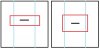
(or acknowledged)I am talking spacing the wheels out further in the y direction, not X. This will give you less bed shake with fast moves. Also having the v rails from 1.0, they are longer than the 1.5 ones and the acrylic pieces underneath can be at least 2 inches longer giving you even more stability.
Attachments
-
 31 KB Views: 3,278
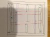
Why not go both wider in the x and y directions then? My next version will replace the lower mdf plate and the acrylic plate in my design with a dual "H" layout something like this. Basically 4 pieces of the wider 20x80 v-slot in an H like this. Have not worked out all the dimentions yet, but I intend to use 8 wheels for improved stability while attaining a more ridgid lower structure and the 3 point leveling. It's not off the table to add additional wheels on the inside of the rails either if needed for stability.
- other Chris
- other Chris
Attachments
-
 40.1 KB Views: 3,277
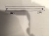
The other idea I'm toying with is to completely simplify the lower piece to a single piece of 3/8" Garolite with the wheels mounted directly to it. Only thing holding me off on this method is finding a way to get the stepper out of the way,which may involve moving it under the lower frame, or to the inside. Have not worked this out completely yet. An easy way to achieve it would be to move to a lead screw for the Y axis, but I think that would be to slow.
Attachments
-
 21.9 KB Views: 3,277
Chris - 1/4" Garolite is more than sufficient. I have several 12"x12" plates from McMaster still sitting around, there's no way you'll get them to bend, and they're flat.
I feel like a broken record here, I keep saying that the way forward is for the bed not to move at all. For the price of an extra motor and 4 more wheels (dual Y axis), you don't get a shaking bed which is the main cause of prints detaching and warping.
A single 20x80 in the middle, clamped to the bottom of the frame right under the motor may work. You can use standoffs if you need to elevate the bed (technically everything will be 1.5 inches lower).
raykholo said:
The 1.0 piece should work as is. You need 1 spacer between the acrylic and the wheel as is openbuilds convention.
I have a rigid MDF plate with 2 wheels on the outside and a 3rd wheel on the inside of the track on each side. The inner wheel uses an eccentric spacer to crank down.
Hand made, works great.
I have a rigid MDF plate with 2 wheels on the outside and a 3rd wheel on the inside of the track on each side. The inner wheel uses an eccentric spacer to crank down.
Hand made, works great.
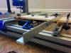
- I did need two 1/4" spacers per v-slot wheel (one extra as each wheel comes with one). This is because on the gMax 1.5 the y-axis motor is inside the frame and the acrylic needs to clear it. Gordon's solution was to split the acrylic into three pieces and layer the center piece above the others to create the extra 1/4" clearance for the center piece (since the acrylic itself is 1/4").
- The mount points for the y-axis belt clip are wider than they were on 1.0, so I had to mark and drill those by hand. In the picture below you can see the original holes just inside the ones with bolts. The distance from center to center of the newer holes is 2.9 inches... I just put the belt clamp on the acrylic, centered it up, and marked it off rather than try to measure 2.9 inches. I drilled with a small diameter bit first because it's easier to get straight. The larger bit followed the smaller hole nicely.
I've attached an image to show the extra spacers, the clearance, and the old belt clamp holes. I need to shorten the bolts I used on the wheels.
Attachments
-
 193.1 KB Views: 3,245
Bring the power supply outside the printer and have it stand on its own. I do that, and one of the Chris-es shows that in the pic of their unit.
I'm talking about the wheel screws. Put a washer under the head of each screw when you flip them around. Prevents burying itself in the plate, distributes the pressure and weight of everything on top of it.
I'm talking about the wheel screws. Put a washer under the head of each screw when you flip them around. Prevents burying itself in the plate, distributes the pressure and weight of everything on top of it.
Christian, I believe the biggest benefits to the upgraded lower section are the stability/ rigidity of the bolt together frame, and the slightly greater Z- height gained by dropping the belt and carriage components. Becuase I built the 80/20 style 5-bolt joint plates w/ leveling feet in the middle to use on mine to stiffen it up, I don't think I will be doing that portion of the upgrade until I do my rev 3 bed re-design. That probably won't be until after the new year at this point.
I hope to be assembling my dual head this weekend (just have to print the fan shroud). I was waiting for Gordon to post a new set of files for the upper end components with the few issues addressed that people had mentioned on the forums here before I jump down that rabbit hole.
As a side note, I found a bunch of aluminum framing cut offs in my garage that I'd stashed after our Solar install earlier in the year. Think I may use that to mock up the H-frame that I want to try for the rev3 bed before spending on phenolic or V-slot. It's a bit heavy, but should at least give me an idea of if I want to pursue the H-frame idea or a solid phenolic plate.
I have to tell you about promotional brochures,anybody knows about it ?