gMax 1.5 and XL
- Thread starter juliatruchsess
- Start date
I have published the rj45 keystone socket and extruder electronics cover tweaks on github and thingiverse. I cleaned up the files a bit and added a second keystone socket to the dual extruder cover (easily commented out if you only want one). Note that I haven't printed the dual extruder file and I haven't checked its clearance around other printed parts or surrounding electronics. The links are below:
Gordon, I've added attribution to your work. If it's not up to par, please let me know and I'll make changes.
- Keystone socket module: https://github.com/marcuswu/RJ45KeystoneReceiver and http://www.thingiverse.com/thing:548145
- Extruder electronics covers: https://github.com/marcuswu/gMaxExtruderRJ45Keystone and http://www.thingiverse.com/thing:548238
Gordon, I've added attribution to your work. If it's not up to par, please let me know and I'll make changes.
I don't know if anyone else had trouble making the dual extruder file from openscad, but here is the finished stl files for dual and single. I have not tried it either as I don't have any keystone jacks. If the file isn't allowed on here go ahead and delete it. Just trying to save some people some time trying to figure out Openscad.
Attachments
-
28.2 KB Views: 94
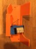
Sorry gents, I printed the dual keystone plate today, and as is it's not going to work as currently designed. See the pic below, but with the angled part of the cover there is not enough room to maneuver the keystone in or wire it once there. I think if the keystone mount was protruded out about a 8-10 mm it could still work. In other words, relative to the picture, move it left so that the back is even with the back of the little vertical flap-thingy above it. Also, at least with my Leviton keystones, the hole was about 1mm to slim to fit the keystone in.
With those tweaks, I think this would rock.
- chris
With those tweaks, I think this would rock.
- chris
Attachments
-
 49.9 KB Views: 3,166
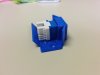
It's hard to tell from the picture which way the keystone should go. The clip should be on the side of the socket that is offset farther. I did have to flex the electronics cover slightly to slide the keystone in at the angle necessary to get the non-clip side of the keystone in place. Then I just rotated it toward the front to clip it in. My plan has been to remove the keystone and wire it up first and then clip it into place.
Here is an image of the keystone clipped into the single extruder's cover from the side. You can tell that I would have had to flex the electronics cover a little bit to get it in there.
Here is an image of the keystone clipped into the single extruder's cover from the side. You can tell that I would have had to flex the electronics cover a little bit to get it in there.
Attachments
-
 49.7 KB Views: 3,160
I updated thingiverse and github with new files because I found a problem with the dual extruder modification. The problem was that the left keystone slot in the picture crussell posted didn't remove the wall to allow the keystone through the opening properly. The right side one in crussell's picture was correct.
Also since proper orientation of the keystone and how I maneuver it into place with the tight fit is not obvious, I decided to post a short video of the process of clipping the keystone in place. It shows the orientation and the actual clipping process. You can see that it does require a little bit of work to get the keystone into position to be clipped. The video is here: https://plus.google.com/108198182381709 ... kwrnbhwEEr
Also since proper orientation of the keystone and how I maneuver it into place with the tight fit is not obvious, I decided to post a short video of the process of clipping the keystone in place. It shows the orientation and the actual clipping process. You can see that it does require a little bit of work to get the keystone into position to be clipped. The video is here: https://plus.google.com/108198182381709 ... kwrnbhwEEr
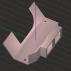
My cousin drew up a modified version of the dual cover/dual keystone based one the work of you gents here. This moves the keystone box outwards to allow more room behind it for maneuvering and cables. The keystone opening is also opened up a smidgen to add a little wiggle room and compensate for shrinkage in the print. Unfortunately, when he migrated this to CAD and made everything solids, he lost the G-max logo (sorry Gordon).
The archive has the scaled .STL and the original .dwg file in it for anyone interested.
- other chris
The archive has the scaled .STL and the original .dwg file in it for anyone interested.
- other chris
Attachments
-
 104.5 KB Views: 1,824
It might be better to bring those keystone sockets back in just a little bit to provide more connecting material between the keystone socket and the electronics cover for strength.
I did not have any trouble with the keystone socket size due to shrinkage. In fact, it worked for me on the first print.
I did not have any trouble with the keystone socket size due to shrinkage. In fact, it worked for me on the first print.