Steps for installing a BLTouch onto a gMax 1.5+
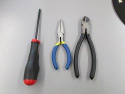
To install a BLTouch on your gMax 1.5+ you will need a screw driver, wire cutters, pliers. You will also need the assembled BLTouch and wires that came with it.
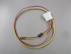
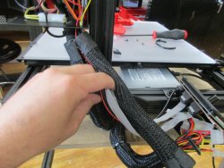
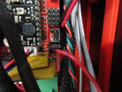
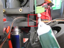
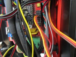
The first piece to install is the BLTouch power wire. This will connect to one of the power supplies molex connectors and will give a dedicated 5v and 12v power source for the BLTouch and other accessories. You will need to remove the LED cover to access the molex connectors.
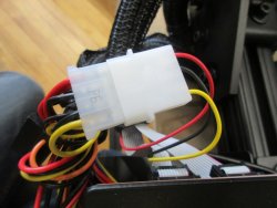
You will need to clip the zip ties holding the TechFlex in place and remove it to expose the wires. This will make it easier to connect the power wire and run it into the electronics box. Connect one end of the BLTouch power cable to a spare molex connector.
Run the BLTouch power wires along the ribbon cables and USB cable and replace the TechFlex. You will then feed the BLTouch power wires into the electronics box. Use 6" zip ties to keep the TechFlex secure around the wire bundle. You can also reattach the LCD cover at this time.
You will then use the pliers to remove the 5v jumper on the electronics board. The single red wire on the BLTouch power wire will then be installed in place of the jumper. Make sure the single red wire lines up with the center pin.
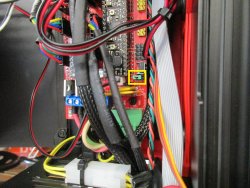
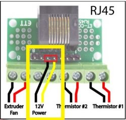
The black and yellow 12v wire will be plugged into the RJ-45 breakout board inside your electronics case. You will need to plug it into the pin above the screw terminals. This wire will give power to the LED light and E3D active cooling fan.
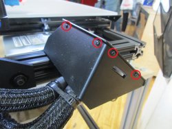
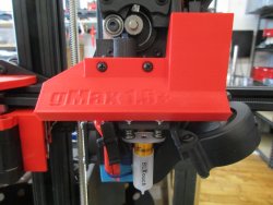
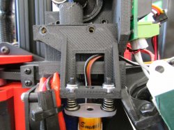
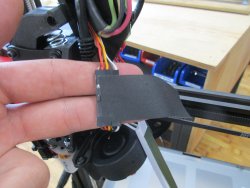
Depending on the style of LED cover you have, you will either need to remove the mounting screws or slide the cover up. If you have the old style led cover, the mounting screws will hold the BLTouch in place. The new style, which slides up, the BLTouch will be mounted on its own.
With the LED cover off, you can feed the BLTouch wires through the slot on the extruder. Make sure to feed the wires straight up when placing the BLTouch. Otherwise, the wires can get pinched between the bracket and the extruder.
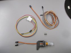
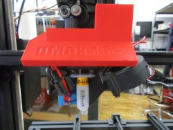
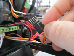
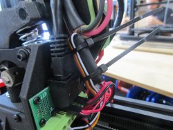
Next you will be using the connector pins to attache the BLTouch to the wires that feed into the electronics box.
To secure the wires in place, wrap a piece of tape around the wires. Flip the connection and zip tie together to help prevent wires from being pulled appart.
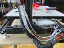
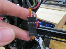
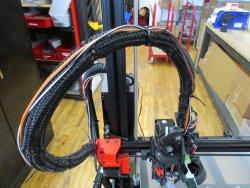
At this point, you will need to run the long BLTouch wires to the electronics box. You will need to either clip the zip ties and run the wires inside of the tech flex, or you can simply zip tie the wires to outside of the wiring bundle.
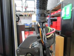
Once you have fed the BLTouch wires into the electronics box, you will feed the yellow, red, and brown wires down the right side. The black and white wire will be fed to the left.
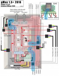
This wiring diagram shows the installation location for all wires involved in with the BLTouch. Once the BLTouch is installed, you will need to make sure you use a firmware that is compatable with the BLTouch.